
+1 877-337-9312 | sale@sflbuild.com

Blog

How to Choose a Wired Push Button in 2026?

Choosing a Wired Push Button in 2026 is not simply a matter of selecting the lowest price or brightest color. The right component must match the equipment, operating environment, and expected service life. A workshop control panel may need a durable metal body, while a compact machine enclosure may require a sealed plastic switch. Small differences matter.

Field technicians usually examine voltage rating, current capacity, contact configuration, actuation force, cable quality, and mounting dimensions. They also check the IP rating when dust, oil, or water is present. A button that feels solid during a quick test may still fail after thousands of cycles. That is an easy detail to overlook. Manufacturer datasheets, certification records, and clear wiring diagrams provide stronger evidence than attractive product photos. Reliable suppliers should explain testing procedures and replacement support.

There is no universal best Wired Push Button. A soft-touch model may suit frequent operator input, but it can be unsuitable where accidental activation is possible. A guarded or illuminated design may improve visibility, although it can increase installation complexity. Even experienced buyers sometimes focus too heavily on specifications and forget the person pressing the button with gloves, grease, or limited visibility. This guide examines practical selection factors for 2026, including safety, durability, compatibility, installation, and long-term maintenance. Some choices will remain judgment calls. That is worth acknowledging before placing an order.
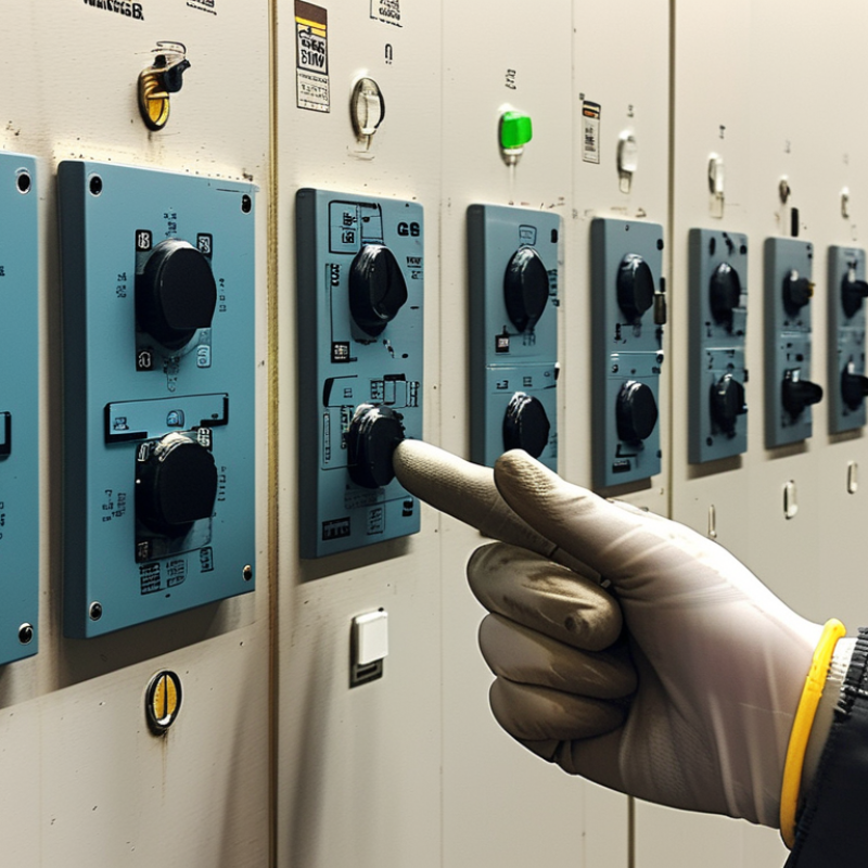
How to Choose a Wired Push Button in 2026?

Understand How Wired Push Buttons Work and Where They Are Used

A wired push button is a simple control device, but its operation deserves careful attention. Pressing the actuator changes the internal contact state. A normally open contact closes the circuit, while a normally closed contact opens it. The button then sends a signal through connected wires to a relay, controller, alarm, or machine input.

Two main designs appear in practical installations: momentary and maintained buttons. A momentary button works only while pressed, like a doorbell. A maintained button stays in its new position until pressed again. Control panels, emergency stop systems, access gates, test stations, and industrial equipment use these options differently. Choose the contact arrangement from the control diagram, not from appearance alone. Small errors here can stop an entire process.

Electrical ratings matter. Check voltage, current, terminal size, insulation, and switching frequency before installation. Outdoor or dusty locations may require stronger sealing and corrosion-resistant materials. A clear actuator color and firm tactile response can reduce mistakes near noisy machinery. Wiring should remain protected from sharp edges, heat, vibration, and accidental pulling.

Do not ignore the operator. A button that feels stiff may slow repeated work. A poorly positioned button can cause awkward reaching. Field experience also shows that labels fade, and assumptions fail during maintenance. Leave space for testing and future rewiring. The “perfect” choice on paper may become inconvenient after months of daily use. Recheck the real environment.

Identify Voltage, Current, Contact Type, and Wiring Requirements

How to Choose a Wired Push Button in 2026?

When choosing a wired push button in 2026, start with the circuit, not its appearance. Read the equipment label and measure the actual control voltage with a suitable meter. Common systems use 12, 24, or 230 volts, but assumptions can damage contacts. Select a button rated above the measured voltage. Allow extra margin for startup surges and temperature changes. That small margin matters.

Check the operating current, especially when a motor, relay, or lamp is connected. A contact rated for resistive loads may perform poorly with inductive loads. Confirm whether you need normally open, normally closed, or changeover contacts. Normally open closes during pressing, while normally closed opens. In field inspections, wiring errors often come from confusing these contact types. I have seen a correct button fail because the load exceeded its DC rating.

Tips: Match the wire gauge to the current and installation length. Confirm terminal markings before tightening connections. Use a suitable enclosure where dust or moisture is present. Do not trust wire color alone. Draw a simple wiring sketch first. Check polarity for DC circuits, then test the button with power isolated. Recheck the circuit after installation, because documentation and real wiring sometimes disagree.

How to Choose a Wired Push Button in 2026? - Identify Voltage, Current, Contact Type, and Wiring Requirements

Selection Dimension What to Identify Common Values or Options Practical Selection Guidance Wiring or Safety Note
Circuit Voltage The voltage that the button contacts will switch 5 V DC, 12 V DC, 24 V DC, 48 V DC, 120 V AC, or 230 V AC Choose a contact rating equal to or higher than the actual system voltage. Confirm whether the rating is specified for AC, DC, or both. AC and DC ratings are not interchangeable. DC arcs generally persist longer, so the DC rating may be lower than the AC rating.
Load Current Normal operating current and inrush current of the load Signal-level loads below 0.1 A; control loads from 0.5 A to 5 A; heavier loads require a relay or contactor Select a button whose rating exceeds both the steady-state current and the switching demand. Use a relay or contactor when the load exceeds the button rating. Motors, solenoids, lamps, and capacitive power supplies can draw substantially higher inrush current than their nominal current.
Load Type Electrical behavior of the connected equipment Resistive heater, LED lamp, motor, solenoid, relay coil, PLC input, or electronic controller Use the manufacturer’s rating for the specific load category rather than relying only on a general resistive-current rating. Inductive loads may need a flyback diode for DC coils, an RC snubber, a varistor, or a dedicated suppression module.
Contact Configuration Whether the circuit should open or close when the button is pressed NO: normally open; NC: normally closed; COM/NO/NC: changeover contact Use NO for a start, trigger, or request signal. Use NC for stop or fault-monitoring circuits where a broken wire should be detectable. Verify terminal markings before wiring. A changeover contact can provide either NO or NC operation, but only the selected terminals should be used.
Switching Action Whether the circuit changes only while pressed or remains changed Momentary; maintained or latching; push-to-make; push-to-break Choose momentary action for a pulse or hold-to-run function. Choose maintained action when the button must retain its state after release. Do not substitute a latching button for a safety-related stop function unless the complete control design permits it.
Number of Conductors The number of separate wires required by the circuit 2 wires for a simple NO or NC contact; 3 wires for COM/NO/NC; additional wires for illumination Count contact terminals and LED or lamp terminals separately before ordering the cable or connector. A lighted button may require a separate pair of wires for the lamp or LED, unless the illumination shares an approved circuit.
Terminal Style How the field wires connect to the button Screw terminal, solder lug, quick-connect tab, spring terminal, or prewired lead Match the terminal type to the available tools, vibration level, wire size, and service requirements. Use the specified wire range and terminal torque. Protect exposed connections against accidental contact and mechanical strain.
Wire Size and Insulation Conductor cross-section, temperature rating, and insulation voltage Common control wiring: approximately 0.2–1.5 mm²; exact limits depend on the terminal Select wire according to current, installation method, temperature, voltage, and applicable electrical codes. The button terminal’s accepted wire range can be smaller than the cable’s electrical capacity. Always follow the terminal specification.
Contact Material and Rating Contact construction and approved switching category Silver alloy contacts for general control; gold-plated contacts for low-level signals; application-specific ratings Use low-level contact specifications for PLC or sensor inputs, especially when current is only a few milliamperes. A high-current contact is not automatically suitable for dry-circuit or very low-current applications.
Ingress Protection Resistance to dust and water at the button face or enclosure IP20 for protected indoor locations; IP54 for limited dust and splash protection; IP65 or higher for dust-tight and water-jet-resistant designs Choose the rating for the complete installed assembly, including seals, cable entries, and enclosure. An IP rating normally applies only under stated mounting conditions. It does not indicate chemical resistance or suitability for immersion unless specifically stated.
Environmental Conditions Temperature, humidity, vibration, dust, chemicals, and outdoor exposure Indoor, outdoor, washdown, high-vibration, cold, hot, or corrosive environments Check the specified operating temperature and mechanical endurance for the actual installation location. Cable glands, gaskets, and strain relief should have compatible environmental ratings.
Mechanical Arrangement Mounting method, panel cutout, actuator size, and required operating force Panel mount, surface mount, flush mount, guarded, mushroom, illuminated, or keyed actuator Confirm mounting-hole diameter, panel thickness range, clearance behind the panel, and accessibility. For emergency-stop applications, use a properly engineered emergency-stop device and control circuit rather than an ordinary push button.
Control-Circuit Architecture Whether the button directly switches the load or only sends a control signal Direct load switching; relay input; PLC input; low-voltage control circuit Prefer low-voltage control wiring and a properly rated relay or contactor for high-power equipment. Keep extra-low-voltage signal wiring separated from mains wiring and use suitable barriers, insulation, and fusing.
Electrical Protection Fuse, circuit breaker, grounding, and accidental-short protection Branch-circuit fuse or breaker; control-circuit fuse; protective earth where required Protect the wiring and connected equipment with an appropriately rated protective device. Disconnect power before installation. Mains-voltage wiring should be installed and tested by a qualified person in accordance with local regulations.
Verification Before Purchase Compatibility of electrical, mechanical, and environmental specifications Voltage; AC/DC current; NO/NC/CO contacts; action type; terminals; wire size; IP rating; mounting dimensions Compare the complete datasheet with the actual circuit diagram and installation conditions. Do not rely on a single headline current rating. Confirm the rating for the exact voltage, load type, switching frequency, and service life.

Note: Electrical ratings, terminal limits, environmental ratings, and installation requirements vary by device design. Always verify the current datasheet and applicable local electrical standards before installation.

Choose the Right Button Design, Materials, Size, and Mounting Style

How to Choose a Wired Push Button in 2026?

Choose the button design based on how people will use it. A flat button suits panels with limited space. A raised button is easier to find by touch. Choose momentary action when the circuit should work only while pressed. Use maintained action when one press must keep the circuit active. Clear labels reduce hesitation, especially in dim workshops.

Material affects service life. Metal handles impact and frequent cleaning well, while engineered plastic can reduce weight and cost. Check the contact rating, insulation quality, and operating temperature before installation. Size matters too. A 12 mm button may suit a compact control box. A 22 mm button offers better visibility and easier operation with gloves. I once chose a small button for a crowded panel. It worked, but it was annoying to use.

Tips: Measure the panel opening, body depth, and wire space first. Confirm terminal compatibility and leave room for strain relief. For dusty areas, consider a sealed design with a suitable protection rating. Choose the mounting style after checking the panel thickness. Threaded mounting works well for drilled panels. Snap-in mounting saves time on thinner surfaces, but it can loosen if the panel flexes. Test the button with the actual load, not only with a meter. Small details matter.

Compare Safety Features, Durability, Smart Compatibility, and Certifications

How to Choose a Wired Push Button in 2026?

A wired push button should protect users before adding smart features. Check the contact design, rated voltage, and switching current first. A normally closed circuit can support safer fault detection in suitable control systems. Look for guarded buttons, clear tactile feedback, and secure terminals. These details matter near machinery, wet areas, or frequent-use doors. Durability depends on more than a strong-looking housing. Check the rated operating cycles, enclosure material, sealing level, and resistance to dust or moisture. A high IP rating helps, but it does not replace correct installation. I have seen durable buttons fail because loose wires created heat at the terminal.

Smart compatibility needs careful interpretation. Many wired buttons work with controllers through dry contacts, low-voltage inputs, or relay modules. Confirm signal type, voltage limits, contact bounce behavior, and cable length. A button may connect physically but still confuse a smart controller. That small difference is easy to miss. Certifications also deserve direct verification. Ask for current test reports and the exact model reference. Check whether the marking applies to the complete product, not only one internal component. Requirements can vary by location and installation category.

Tips: Press the button repeatedly with a gloved hand. Inspect terminal access and cable strain relief. Test the circuit after power loss. Do not trust a certificate image alone. Compare the document number, product variant, and issuing laboratory. A short installation trial may reveal problems that specifications hide.

Verify Installation Conditions, Maintenance Needs, and Total Cost in 2026

How to Choose a Wired Push Button in 2026?

Choosing a wired push button starts with the installation environment, not the appearance. Check the panel cutout, mounting depth, cable entry, and available terminal space. Dust, moisture, vibration, and outdoor temperature can quickly affect performance. A button for a clean control cabinet may fail beside a washdown area. Confirm the voltage, current rating, contact configuration, and expected switching frequency before purchase. I once overlooked cable bending space, and the installation became unnecessarily difficult.

Maintenance needs also influence the real cost. Inspect terminals for looseness, check the actuator for sticking, and remove surface contamination with approved methods. Avoid aggressive solvents unless the technical documentation permits them. Record operating cycles and replacement intervals when the button controls frequent machinery. The cheapest unit may require more labor, more spare parts, and longer downtime. Include wiring, enclosure changes, testing, and technician time in the calculation. My earlier estimates ignored downtime, which made the “low-cost” option less economical.

Tips: Measure twice. Photograph the existing wiring first. Keep one tested spare on site. Confirm that replacement contacts match the control circuit. If conditions are uncertain, trial the button in the actual location for several days. Do not rely only on catalog images. Ask for drawings, terminal details, ingress information, and installation limits. Small omissions can become expensive corrections.